Dakota Digital 2000 Series Specifications

Browse online or download Specifications for Motorcycle Accessories Dakota Digital 2000 Series. Dakota Digital 2000 Series Specifications [en] [fr] [it] User Manual

  • Download
  • Add to my manuals
  • Print
  • Page
    / 10
  • Table of contents
  • BOOKMARKS
  • Rated. / 5. Based on customer reviews
Page view 0
MAN# 650023B
1
Universal Gear Shift Sender
GSS-2000
The easiest system to install and use on the market.
The Dakota Digital universal gear shift sender consists of three main components; the sensor,
decoder, and mounting brackets. The sensor mounts to the transmission and converts the transmission
linkage arm position into an electrical signal. The decoder converts the electric signal from the sensor into
the individual outputs for each gear and provides the neutral safety and backup features. The outputs are
selectable for positive or negative outputs. This unit can also support single-wire indicators from Dakota
Digital, Inc. The mounting brackets attach the sensor to the transmission housing and linkage arm.
The only parts of the gear shift sender that are different for the different transmissions are the
mounting brackets. The GM 350, 400, and 700-R4 use the same linkage connector and mounting plate,
but different holes in the mounting plate. The Ford C-6 and C-4 each have different mounting plates and
linkage connectors. For other transmissions, a universal mounting plate is provided.
and 'START' positions
fused +12V with key in 'ON'
To ECM Park-Neutral input (optional)
To neutral safety relay (optional)
To back-up lights (optional)
to sensor RED wire
to sensor GREEN wire
to sensor BLACK wire
to Chassis Ground
BACKUP
POWER
GROUND
SAFETY
DIM
PARK
REVERSE
NEUTRAL
OVERDRV
DRIVE
SECOND
FIRST
1-WIRE
RED
GREEN
BLACK
Dakota Digital
GSS-2000 DECODER
B.U. PWR GND N.S. SW
DIM PARK REVERSE NEUTRAL OVRDRV DRIVE SECOND FIRST 1-WIRE
INDIVIDUAL
BULBS
STR
SYSTEM
DGS-1
VFD/VHX
SYSTEM
ODYR/SLX
GAUGE
DGS-3
DGS-4
LOKAR
(- OUT)
PARKING
LIGHTS
NOT
USED
NOT
USED
NOT
USED
NOT
USED
NOT
USED
NOT
USED
NOT
USED
NOT
USED
PARK
TERMINAL
REVERSE
TERMINAL
NEUTRAL
TERMINAL
OVRDRV
TERMINAL
DRIVE
TERMINAL
SECOND
TERMINAL
FIRST
TERMINAL
GREEN
WIRE (+)
GRAY
WIRE (+)
PURPLE
WIRE (+)
YELLOW
WIRE (+)
ORANGE
WIRE (+)
BLUE
WIRE (+)
BROWN
WIRE (+)
NOT
USED
NOT
USED
NOT
USED
NOT
USED
NOT
USED
NOT
USED
NOT
USED
NOT
USED
NOT
USED
NOT
USED
NOT
USED
NOT
USED
NOT
USED
NOT
USED
NOT
USED
NOT
USED
NOT
USED
NOT
USED
NOT
USED
NOT
USED
NOT
USED
RED
WIRE (+)
GEAR
TERMINAL
White/Green
WIRE
YELLOW
WIRE
PARKING
LIGHTS
PARKING
LIGHTS
NOT
USED
GREEN
WIRE (+)
NOT
USED
DGS-2
PURPLE
WIRE (-)
YELLOW
WIRE (-)
BLUE
WIRE (-)
BROWN or
NOT USED
ORANGE
or BROWN
WHITE or
ORANGE
GREEN or
WHITE
GRAY
WIRE (+)
PURPLE
WIRE (+)
YELLOW
WIRE (+)
ORANGE
WIRE (+)
BLUE
WIRE (+)
BROWN
WIRE (+)
RED
WIRE (+)
RED
WIRE (+)
RED
WIRE (+)
RED
WIRE (+)
RED
WIRE (+)
RED
WIRE (+)
TYPE OF INDICATOR SYSTEM
Programming Switch
Programming LEDs
Page view 0
1 2 3 4 5 6 7 8 9 10

Summary of Contents

Page 1 - GSS-2000

MAN# 650023B 1 Universal Gear Shift Sender GSS-2000 The easiest system to install and use on the market. The Dakota Digital universal gear shift

Page 2

MAN# 650023B 10 TROUBLE SHOOTING GUIDE Problem Cause Solution None of the lights will come on. Power wire not connected. M

Page 3

MAN# 650023B 2 PARTS LIST description quantity gear shift decoder 1 relay for neutral safety 1 gear shift sender with 1

Page 4

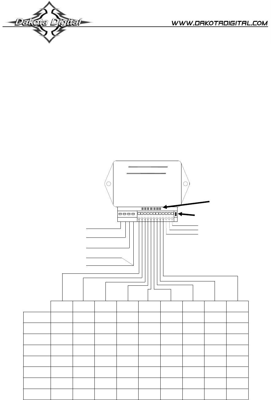
MAN# 650023B 3 PROGRAMMING THE GEARS Programming is done using the set switch, small switch on the decoder located by the sensor connection termi

Page 5

MAN# 650023B 4 Ignition SwitchStarter SolenoidCut wire between starter solenoid and the wire that feeds it from the ignition switchBLACKBLUE868785

Page 6

MAN# 650023B 5 MOUNTING SENSOR TO TRANSMISSION. The diagrams on the following pages show the mounting hardware used and mounting location for the

Page 7

MAN# 650023B 6 Mounting to a GM 350, 400, or 700-R4 transmission.

Page 8

MAN# 650023B 7 Mounting to a Ford C-6 transmission Depending on the shifter you are using, you may use the linkage connector provided. The bott

Page 9

MAN# 650023B 8 The GM, Ford C-6, and universal mounting plates secure to the transmission oil pan using the supplied 1” bolt, spacer, and washer p

Page 10 - MAN# 650023B

MAN# 650023B 9 Mounting to a Ford C-4 transmission This mounting plate connects to the lower two bolts of the four bolt plate located on the lef

Comments to this Manuals

No comments